
FAQs
Roll Forming Lines | Systems | Roll ToolingFrequently Asked Questions About
Roll Forming and Kolev Engineering Inc.
Getting
Started
What is roll forming?
Roll Forming is a progressive motion process of forming flat strips of cold sheet metal through several stages of forming or bending, thru pairs of rolls, gradually without changing the thickness.
Henry Court (1740-1800), an English inventor, introduced the technology of rolling using rolls by forming the red-hot iron into bars, in 1783. His first rolling mill introduced grooved rollers to produce iron bars more quickly and economically than the old methods of hammering. His invention revolutionized the British iron industry.
The idea of forming by rolls has been developed further and applied for cold forming as well. Today’s modern cold roll mills are used to bend and form sheet metal through several rolling dies stands in great quantity and speed. Complex metal-formed parts and cost effective production in big volume is what established the roll forming industry and took a significant market share in metal forming.
What are advantages of the roll forming technology?
The technology of Roll Forming offers great advantages versus press brake forming.
No 1. Volume
An investment in a new roll forming line is justifiable when you have a great volume of parts estimated in linear feet (i.e. 1,000,000 feet per year) or in metal [steel, aluminum] weight. Most roll forming companies are estimating their profit as a % of the weight for the total purchase order. If you estimate your volume based on weight, the speed of the roll forming line is essential. Heavy gauge rollforming lines, at high speed, cost significantly more, but if the total metal weight rollformed for a certain period of time is what pays the bills and keeps the profits high, it is an efficient ROI.
No 2. Ability to produce variety of shapes in the same Roll Forming machine [rollforming line]
By changing the roll tooling in the rollforming machine, changing the cut-off Die (or just the cut-off shear blades), you can produce parts with a different shape. The cost of the new roll tooling and Dies is added to your selling price, unless your customer would like to be the owner of the tooling and pay for it.
No 3. Ability to produce parts of similar shape with the same Roll Tooling
- Different part web
- Different legs
- Specific part members
We design combination split rolls, and by changing certain rolls we change certain segments features of the roll formed part. Another technique is using quick change spacers to re-arrange the rolls and have different dimensions of the segments. If we have to design a combination set of roll tooling for similar shape parts, a separate set of shear blades for the cut-off system will be required for each size.
No 4. Ability to produce parts at variable length
Cut-off systems are part of the roll forming lines. In a post-cut line configuration with a flying shear or cut-off die, the cut length is pre-set automatically. The electrical controls are designed and programmed to perform different jobs defined by the part’s quantity and length. In Europe and Asia, still, many post cut rollforming lines are designed and build type Stop and Go. The cut off die is stationary and the Rollformer works on start and stop mode. Speed limits in stop and go lines are 45mpm max., for 10ft length. And both types depend on an encoder to activate the cut-off process and the part to be cut at a specific length. Length tolerances for the different industry are different.
No 5. Smooth surface on the finished product
Once the roll tooling is designed and manufactured correctly, the finished surface of the product is smooth without scratches or wrinkled sections. Any marks at the corners must be acceptable if the application has no specific requirements. The roll tooling material we use is mostly D2 and performs perfectly without leaving unacceptable marks on the material. In some special cases forming pre-paint material, the rolls are flashed, chromed, and polished. To avoid any surface marks, an additional technology of laminating the metal strip before roll forming is used, covering with a thin plastic layer on both sides, i.e. stainless steel parts for the automotive industry.
No 6. Forming parts with different thickness – 0.005”–0.500”
The material thickness range in the rollforming industry is between 0.005” to 1/2”. In rare cases, the material can go 3/4” or above. When we configure and size the equipment, we size it for certain material thickness range. The advantage is that with the same set of rolls, parts with a specific material thickness range can be manufactured. But the thickness range within is not advisable to be more than 2 times.
No 7. Integration of additional operations in line
Another great advantage of the rollforming technology is adding features to the parts being formed. Within the rollforming line, we add specific tooling and associated equipment to do:
- Notching of edges
- Piercing of holes
- Embossing
- Knurling
- Lansing
- Welding – spot, laser, high-frequency welding, etc.
No 8. Post-secondary operations off line
After the parts are roll formed and cut to length, they can proceed further to post-secondary operations for additional press forming and specific piercing. One of the first post-secondary machines I designed was for wire mesh decks “reinforcing channels” that required 3 post-secondary operations: spread the ends, bend ends to L shape, and pierce mounting hole. These machines well served the wire mesh decks manufacturers.
No 9. Rollforming as a part of a complex automated technology with special purpose machinery
For example, manufacturing steel doors requires rollforming the longitudinal edges of the steel panel and is one of the fourteen line operations. This complex assembly door line (Fig.1.1) from start to finish has a bending operation, which for line speed purposes instead of press brake bending is done by a Rollformer between the other special purpose automated machinery.
No 10. Sufficient cost reduction
Cost reduction depends on volume and volume depends on rollforming line speed. High speed rollforming lines are more expensive, but ROI is faster and with great benefits in a long run. Compared with press brake forming, the cost easily is reduced with minimum 15% to 25%. Average rollforming speed range is 100–250ft/min. High speed can reach 300–450ft/min., i.e. stud/tracks roll forming machines. When you are calculating the projected cost reduction based on volume, you must consider that the efficient roll forming time is 60% only in an 8 hour shift. Still speed is in relation with the part complexity, sensitivity, and heat anticipation and certain rollformed parts have speed limit established through the tryout process.
What kind of materials can be roll formed?
Materials that can be rollformed are:
- Carbon steel – hot or cold rolled
- Stainless steel
- Aluminium
- Copper
- Pre-painted steel
- PVC coated steel
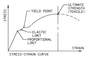
In order to rollform we are looking at the formability of the material and spring back effect.
Mechanical property of the material – yield and tensile strength is important to establish the rollforming process, to design rolls and size a complete rollforming line for specific profile with specific features.
Material can be with:
- strength range – from 35-120ksi yield, different thickness 0.005” to 0.500”,
- different width – from ¼ to 54” (panels rollforming – corrugated, doors, cable trays etc.)
- coated – pre-painted, galvanized (zinc), vinyl protection layer prior to rollforming
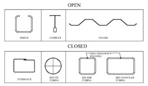
What shapes can be produced with rollforming?
We have two major categories:
A. Open
B. Closed
Additionally between them they are divided on:
For the category of open profiles:
- Simple – with one to four bending corners.
- Complex – with multiple bending corners and hemmed edges, combination between open and closed.
- Panels – wide profiles with corrugated trapezoid or wave shapes, locking ends, door panels, electrical wide trays, special.
For the category of closed profiles:
- Interlocking – square, rectangular, polygons, round or special shapes
- Tubes – round, square, rectangular, welded seamless tubing
Can I ask a question related to my rollforming needs?
If you have any question related to your rollforming needs, our technical experts will answer all of them and offer a solution that will fit your budget.
Please send us an e-mail to koleveng@kolev.com
Or call +1 905 751 0339
We guarantee best value on a new rollforming system.
Design
What equipment normally makes a rollforming line?
Rollforming line is configured and sized based on the part being rollformed with all features and specifications – pre-punching, notching, in line welding, inline slitting, and post cutting, material handling, post secondary operations.
LIST OF EQUIPMENT FOR ROLLFORMING LINE CONFIGURATION
- Uncoilers
- Coil cars
- Seizer or treaded tables
- Flatteners/Levelers
- Feeders – Servo
- Flatteners – Feeders combination
- Pre-punching presses – hydraulic, mechanical, air
- Punching, pre-notching tooling – Dies
- Roll Forming Machines
- Cut-Off Systems
- Packaging systems
- Additional inline operations – Curving, welding, embossing, lansing, printing etc.
- Special purpose machinery for post-secondary operations
By type of operation, rollforming lines are designed Pre-cut and Post cut
1. PRE-CUT OPERATION
In this type of operation (Fig. 1), the sheet metal is cut to length prior to entry of the rollforming machine. It is used to roll form parts with complex shape where cut-off would be an issue.
The advantage is that the exit cut-off system is eliminated, there are no cut-off dies to change, or expensive cut-off blades.
The disadvantage is that this type of rollforming line will require Rollformers with 1/3 more rollforming stations and rolls to keep control and pull out of the machine the rollformed part. Trapping and guiding the material from the beginning almost to the end is a necessary rolls design feature that cost extra rolls.
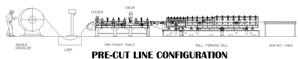
Fig.1
2. POST-CUT OPERATION
Most of the rollforming lines are designed with post cut operation – Fig.2.
They are designed and configured in 2 modes: Loose and Tight
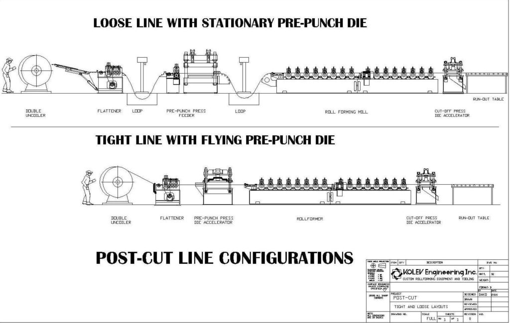
Fig.2
2.1 Loose
Typical loose line configuration:
- Uncoiler
- Straightener/flattener
- Strip Loop control
- Pre-punch press with servo feeder and pre-punch/notching die
- Strip Loop control over a pit accumulator
- Rollforming machine with entry guide, exit straightener, and encoder fixture
- Cut-off Press with Cut-off/shear Die on a fly (Die accelerator)
- Run-out conveyor
In loose line, the material is pulled from the Uncoiler by a driven straightener. Loop control keeps the sheet loose between the straightener and pre-punching/notching station. The pre-punching station is a combination of a press with accommodated punch/notching die and the material is fed into it by a servo feeder, mounted at the entry side of the press. By creating a loop, the servo feeder will have less resistance when a feeding is in motion with precision progression.
Second loop between the pre-punch press and Rollforming machine is needed to establish an adequate timing for the pre-punch press to complete its cycle without the Rollformer, to pull the material and interfere with the pre-punching process. Minimum and maximum loop is established and Rollformer speed is set up within the loop range. After the Rollformer, the part is entering the exit system – cut-off press with flying cut-off die accelerator (or stationary if the post cut line is in mode “STOP and GO”) and proceeds further to material handling system.
2.2 Tight
The idea of tight line is to speed up the rollforming process and eliminate the expensive servo feeder application. The pre-punch press is built with Die accelerating mechanism and pre-punching operation is completed on a fly. The tolerances of the punching pattern usually are loose.
Additional operations can be added inline, such as: welding, slitting, swiping, curving, printing, Lansing, embossing, stitching, etc.
Can you design and make only the rollforming rolls?
One of the essentials of our business is designing complete set of rolls for a specific rollforming machine.
Designing rolls is the art of the rollforming.
We are well known that our expertise in design and manufacturing Roll Tooling features:
“First tryout – Right part”
Our customers are specializing on specific family of rollformed products and are already equipped with the required rollforming equipment.
Introducing new roll formed part in their industry requires investment only in a new set of rolls and cut-off dies, or just shear blades.
For inquire of your new rollforming set of rolls please contact us at:
koleveng@kolev.com
+1 905 751 0339
And send us a drawing of your rollformed profile.
Do you design custom roll forming parts?
We do not design custom roll forming parts.
We can only advise how the part can be designed for the purpose of rollforming in order to avoid undesirable side effects.
Basic principles of designing parts for the technology of Roll Forming
When designing parts for rollforming, you must be aware of:
1. Cross section depth
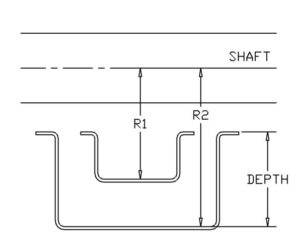
Fig.1
- Part depth determines Roll’s Diameter – Fig.1 The deeper the cross section, the bigger the Roll’s diameter, and controlling the shape of the part is more difficult. In a case of roll forming a part with deep cross section it’s recommended to use rollforming machine with ratio bottom to top shafts – 2:1; 1.5:1; 1.33 or any custom ratio. It will reduce bottom rolls diameters and size of the Roll former. Deeper cross section will require more passes for smooth run. It is even more complicated if the part is not symmetrical.
- Deeper cross section will require sufficient distance – vertical (bottom to top shaft) and horizontal (pass to pass)
- The cost for the Roll Tooling is higher (if it can fit to an existing Roll Mill. Otherwise a new Roll Mill will be required with a specific custom configuration to meet the part’s design requirements).
2. Web length or flat area
When the part is designed for rollforming technology, the following should be considered:
- Fig.2a Length of the flat area. Wide flat cross sections will cause wrinkled surface, and oil canning.
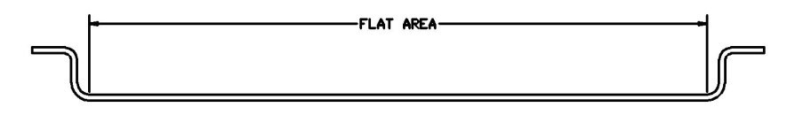
Fig.2a
- Fig.2b If having a wide flat cross section is absolutely necessary – consider flattening Rolls (i.e. after roll forming, the part is additionally bent and cut through a progressive Die in 2 or 4 pieces.) If the panel is not formed in a duplex Rollformer but conventional, consider using support rolls in the middle.
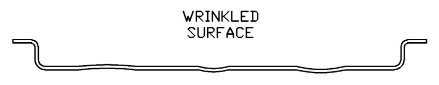
Fig.2b
- Fig.2c If the desired wide flat area is not of importance for assembly purposes – consider adding grooves (arcs, triangle or rectangular shape) for stiffening. Too many grooves as well may cause cross bowing. One or two grooves are desired in the middle of the web.
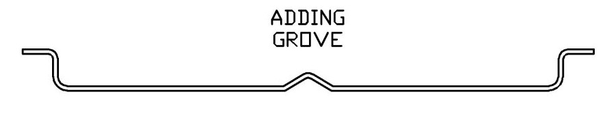
Fig.2c
3. Piercing, notching, holes pattern
In rollforming, strain is the worst enemy, and having openings in the material often creates unpredictable side effects. In product design (see Fig.3, it is mandatory to consider the following when holes need piercing or edge notching is required:
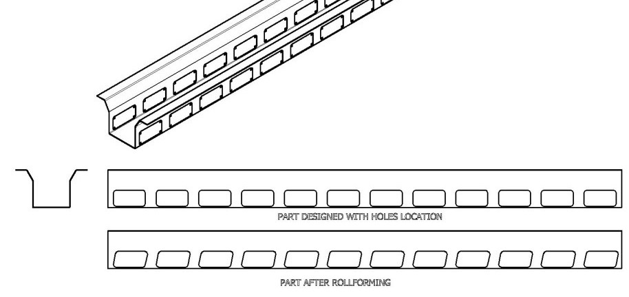
Fig.3
- Holes must be at least 3–4 times the material thickness away from the line of bending.
- Holes must be at sufficient distance from the cut edge.
- Holes close to the part edges will cause wavy edges.
- Round holes at the line of bending will be distorted into an oval.
- Having edge notching is considered forming a precut material. The continuity of the strip strength is disturbed and more rollforming stations are required – up to 1/3 more.
4. Minimum Radius of bending
Bending Radius
Common radius – Fig.4 a-b – minimum bending radii for forming are provided by the metal supplier or are specified in standards.
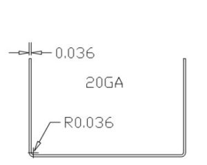
Fig.4a
- The usual minimum bending radius for mild steel is equal to the material thickness.
- In certain conditions it can be 0 degrees
- For high strength steel, low elongation material, the minimum radii must be 4–8 times material thickness.
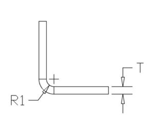
Fig.4b
Large Radius
Rollforming is based on the principle that the metal attains permanent deformation at the bend lines – outside fibers strained and inside fibers compressed beyond yield limit. If the metal does not stress beyond the yield limit, it will spring back into flat position.
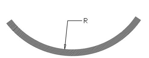
Fig.4.2
Forming large radii (Fig.4.2), the tension and compression in the outside fiber can be so small that permanent deformation is not reached. That’s why it is very difficult to rollform metals to reasonable tolerances if the bending radius is 10–100 times or more the material thickness.
Small Radius
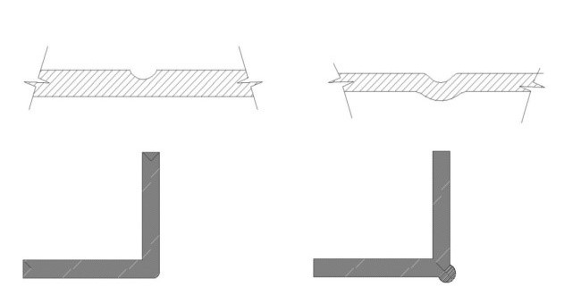
Fig.4.3
- Very small radius or even 0 degrees can be achieved by hemming, or by special grooving (Fig.4.3)
- Attention is to be paid to strip calculation – add extra material
- At bending line there will be reduced material thickness (expect cracking)
5. Dimensioning parts for rollforming
When design of a part is completed, it is important for the purpose of roll tooling design to establish GDT – general dimensions and tolerances. For assembly purposes, the end user knows.
- which dimensions are important and have to be held within the tolerances
- in which direction the material thickness “grow”
(when minimum and maximum material thickness is established)
For example: If the web dimension is for track application, must be shown inside of the part – Fig. 5.1. Material thickness increase can only go outside.
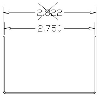
Fig.5.1
And if the web dimension is for stud – Fig.5.2 – it is essential to be shown outside of the part. Material thickness increase can only go inside.
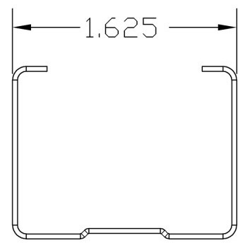
Fit.5.2
6. Tolerances
For the purpose of high volume of production (high speed), acceptable tolerances are required in order to justify the technology of rollforming. Depending on the application, the rollformed products can have:
- Loose – +/- .030”-.040”
- Medium – +/- .015”-.025” (average in the industry)
- Tight – +/- .005” (i.e. parts for automotive industry)
Length tolerances
Length tolerances are important for choosing the right die accelerating system.
If the tolerances are within 0.015”, the length measuring system must be “close loop.” The design of this type of cut-off system is required to implement servo motor where the die acceleration is with timing belt, ball screw, or rack and pinion drive components.
- If the length tolerances are “loose” – open loop measuring system will do the job. The Die accelerating systems in this case are designed with air accelerating cylinder or with spring die return. Spring die return is the least expensive solution and works in slow speed rollforming, where the cut-off knife penetrates into the part and drags the die till it releases it when knife strokes out.
- Positive stop and special features for cut-off die dragging. In slow speed where more precision cut to length is required, there is a solution with positive stop or picking mechanism. The picking mechanism is part of the cut-off die, grabs the part in specially designed and pre-punched hole(s), and drags with the part till cut is completed.
Surface appearance tolerances
- Hot rolled and even cold rolled steel is less sensitive to surface scratches. Still, traces of marks in the corner areas can be detected easily; the question is: are they acceptable for the final product appearance or does the process of forming need to be revised and reduce such marks?
- Pre-painted metal, high luster stainless steel, or aluminum has to be carefully formed to avoid scratches. It is a good practice to consider more passes, different tool steel and/or surface finish. Flush chroming on the rolls is well proven to work with pre-painted material. D2 is most preferred tool steel.
- Rollforming 302/304 stainless steel for outdoor application. I had the experience of forming panel 302 SS material with D2 rolls in the field. Even after forming, the part’s corners were brushed and acid cleaned, the carbon from D2 left over the smashed stainless steel layer, 6 months later start showing signs of rust. Then we decide to change the rolls with stainless steel rolls, special grade, and the rust effect was resolved.
6. Min/Max Material thickness relationship
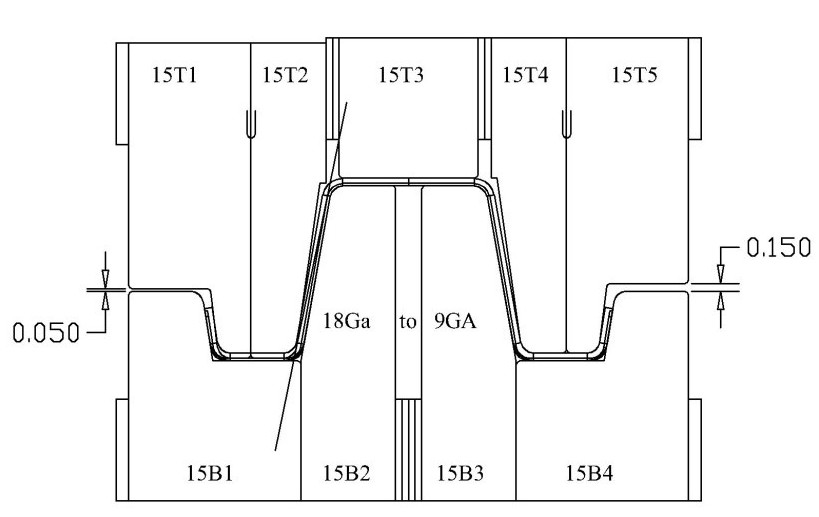
Fig.7.1
Within one set of roll tooling, we can manufacture the same part with different material thickness. By bringing down the top rolls, we set up the rolls for thinner material. What is important to understand is that the material wraps around the roll’s corners but the vertical gap for maximum material thickness is not fulfilled – thinner material goes diagonal. If we need to have total control, the rolls must be split and with quick change spacers (shims); the gaps have to be closed.
What is needed for a good rollforming design?
In the roll forming industry, it is a common knowledge that a good roll formed product (RFP) is in function of the following variables:
RFP = f (RFM, RT, RFL, RFP, D, RFPS, M, L, EC)
RFM – Roll forming machine – type and design features variables:
- Specific types of Rollformers are appropriate for certain types of rollformed parts. A proper match between part being rollformed and the Rollformer’s design configuration and sizing is required for quality production. Often, brand new Rollformers are designed and built just to suit a specific part with all its features, especially for RFP that are with complex shape and tight tolerances.
- Horizontal distance from pass to pass – it is important for material edges stretching.
Condition of the machine – bearing blocks condition, alignment, shafts condition (if deflected), etc.
- Quantity of Passes – there is always a dilemma if an existing Roll forming machine with certain quantity of passes will accommodate certain profile – if the machine is short on passes, the profile can still be produced, but will give you limitation in quality and speed – something will be sacrificed.
RT – Roll tooling with the following variables:
- Roll Tooling Design – good or bad design
- Roll tooling material – less expensive Roll tooling materials after a certain period of time start to pick up on material, wear out quickly, and decrease part quality.
- Roll tooling manufacture – questions: are all dimensions held correctly? Is the technology of manufacture completed or are certain procedures missed?
- Roll Tooling proving – in the process of roll tooling development, all coil strip width and material thicknesses must be compensated in the roll tooling
RFL – Roll forming line configuration variables:
- Is it a tight line?
- Is it a loose line?
- Does the line require pre-notching or punching? It is important based on the cut to length what kind of feeder is used.
- What is the cut-off system – Servo acceleration, Air cylinder, or drag with spring return?
RFP – Roll formed product variables:
- Profile shape – is it simple, medium complex or complex?
- RFP tolerances – loose – +/- 0.060”; medium tight – +/- 0.030”; tight – +/- 0.010”
Note:
- RFP with tight tolerances require Roll Forming Machine with more passes than usual.
- RFP with complex shape and tight tolerances will require at least 1/3 more passes and lower speed.
D – Dies – Pre-punching/notching and Cut-off Dies
- All pre-punching/notching operations are creating additional stress around the cut edges that later, inside of the Roll forming machine, shows tendencies of relieving that stress and works against the shape of the Roll Forming product.
RFPS – Roll Formed product sensitivity:
- The final product is always sensitive to shortage of rollforming stations and the Rollformer speed. Heat anticipation in the parts corners is causing side effects.
M – Material that is roll formed. It is important to understand that the final dimensions depend on:
- Material mechanical properties
- Tolerances on the material after tension leveler proceeding and slitting – all deviations in thickness work against the Roll forming machine, and all deviations in width, camber and coil set of the strip are working against the Roll tooling (if the roll tooling can compensate those deviations)
L – Lubrication or cooling during rollforming:
- Based on the material being roll formed, certain lubrication is required to avoid material pick up on the rolls or for coolant to cool as much as possible the roll formed profile and avoid side effects such as bowing and twisting as a finished shape after it cools off completely.
EC – Electrical controls:
- Choosing proper methods of measuring controls will improve the length controls and notching/punching progressions.
- Servo Die acceleration vs. Air cylinders Die acceleration?
- Encoders vs. sensors (The encoder sooner or later will have slide slippage on the material and gives faulty readings)
In trouble shooting, all the above variables can be narrowed down to 3 major variables in the quality formula:
(1) Roll Forming machine condition,
(2) Roll Tooling – inspection, set up and design review,
(3) Material being Roll Formed.
Production
Where do you manufacture the rollforming machines?
We proudly manufacture our rollforming machines in Mississauga, Ontario, Canada
How long on average takes to do roll tooling?
Average time for design and manufacture set of roll tooling is 8-10 weeks.
If there are additional side rolls fixture that has to be designed and manufactured, time estimation is based on the complexity of the rollforming technology for a specific rollformed part.
What steel do you use for roll tooling?
All our roll tooling is manufactured with D2 steel.
We do not cut corners and supply rolls with D2 material that is proven to last, works perfect with pre-painted materials, stainless steels without leaving marks on the material.
We do not use 4140HT and then chromed or any similar combination that is a recipe for failure.
Unless it is a specific request, our preference is D2.
Generally in the industry Rolls are manufactured with different tool steel and are based on the application, life to last, and price.
Most common tool steel used is:
- 1045
- 4140
- 4340
- 8620
- 52M
- L6
- A2
- O1
- D2
Can you ship internationally?
All our equipment is sold FOB.
We can assist you and arrange a shipment to the port of entry requested
Payment
What initial payment is required to start a project?
Terms of payments are variable and specified in our quotations depends on the job size.
Standard is:
25% down payment
25% progressive payment with design completion and material purchase
25% progressive payment with job completion prior for tryout
25% prior to shipping
Do you take purchase orders?
In order a project to kick-off a written purchase order and initial down payment is a must.
Delivery time is count after all requirements are completed by the customer.
How do I go about making payment?
We do accept checks for North America and wire transfer internationally.
No credit cards.
Warranty
What is the warranty on your rollforming machines?
The warranty is stated in our standard terms and conditions of sale as a part of our Quotations:
Warranties
There are no warranties Express or implied made by KOLEV except for their following standard warranty; KOLEV warrants new and unused equipment, machinery designed and manufactured or manufactured only, against defects in material and workmanship caused by normal use and service, for a period of one (1) year from date of original use, but not to exceed eighteen (18) months from the date of shipment from our premises. The obligation under this warranty is limited to the replacement or repair of such parts deemed by us to have been defective at the time of sale. Any alterations or charges to the product design by the customer invalidate any warranty claims. We reserve the right to inspect any defective part claims. Before such parts are returned to our premises, our written approval must be obtained and the parts then returned at the customer expense. Products not manufactured by us are subject to the original manufacturer’s warranty only. Warranty does NOT cover wear and tear items such as: Roll Tooling, Dies with its components – punches, cut-off blades etc that are subject to production use and operator’s care.
Still need help? Send us a note!
For any other questions, please write us at sales@kolev.com or call us at: 905-696-0339
![]()
![]()
![]()
![]()